
User Manual – Bluetooth Low Energy Dimmer
Last revised 17 July 2017.
Notice: The dimmer can only operate with 0-10V dimmable LED drivers. PWM dimming is not supported.
Black: Line
White: Neutral
Green: DIM+
Grey: 5V Input

Specs
Bluetooth Low Energy Dimmer
Hardware
Bluetooth V4.2
Universal 100-375VAC, 50/60Hz
0-10VDC, 20mA dimming output
18 AWG wires (Line, Neutral, DIM+, DIM-)
Dimensions (Length x Width x Height) 100mm x 50mm x 25.5mm
Firmware
Built-in BLE Stack
Certifications
ETL
CE
FCC
IP55
Installing the BLE Dimmer
The following is the installation process of connecting the BLE Dimmer to its corresponding lighting fixture.
DANGER: RISK OF ELECTRIC SHOCK. DISCONNECT ALL SOURCES OF SUPPLY BEFORE SERVICING.
Download
1. Connect BLACK wire to the LINE input of the LED driver. LINE is also the line of the main AC power.
2. Connect WHITE wire to the NEUTRAL input of the LED driver.
3. Connect the green DIM+ wire to the DIM+ input of the LED driver.
4. Connect the grey DIM- wire to the DIM- input of the LED driver.
5. Position and secure BLE Dimmer near lighting fixture.
Controlling the BLE Dimmer
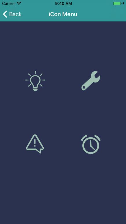
The iCon Menu
The iCon Menu screen is the main screen of the mobile app. From this screen, the user will be able to navigate the app by accessing other screens.
Top Left: Lightbulb – Dimmer Control screen
Top Right: Wrench – Zone Setup screen
Bottom Left: Exclamation Mark – Factory Erase screen
Bottom Right: Clock – Zone Alarms screen
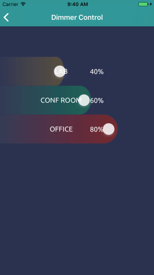
Dimmer Control Screen
On the Dimmer Control screen, the user will be able to adjust the brightness of each individual zone in the network. Each zone has an individual slider that can be adjusted from 0% to 100% brightness.
1. To adjust the brightness of a zone, hold and drag the end of the slider left or right to decrease or increase brightness.
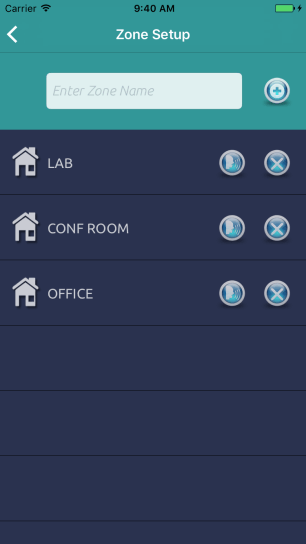
Zone Setup Screen
On the Zone Setup screen, the user will be able to manage the network of zones by creating and deleting zones.
1. To begin creating a zone, ensure that all dimmers associated with the zone intended to be created are turned on. All dimmers not intended to be associated with this new zone must be powered off.
2. Once completed, begin typing the zone name into the "Enter Zone Name" field at the top of the screen. Select the ✙ button to create the new zone.
3. Once the iCon has retrieved all information for the new zone, the lights of the new zone will repeatedly turn on and off for about 5 seconds. The dimmer will then set the lights of the new zone to maximum (100%) brightness. The zone is now successfully programmed.
- - -
1. To add a new light to an existing zone, first ensure that the dimmer of the new light and lights in the existing zone are powered on. All other lights should be powered off.
2. Select the sync button (talking face icon) that corresponds with the zone you intend to add the new light to. This will now re-create the zone with the new light included.
- - -
1. To delete an existing zone, simply select the x button that corresponds with the intended zone.
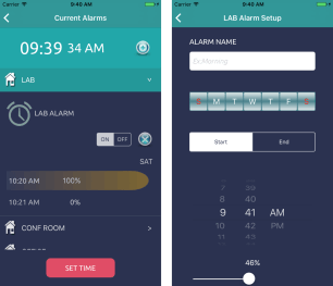
Zone Alarm Screen
On the Zone Alarms screen, the user will be able to schedule when certain zones will be powered on and off and adjust the brightness of each zone at any given time. Alarms can be set by the minute for any day of the week.
This screen displays all the different zones in the network. When a zone is selected, any alarms set for that zone will drop down and be displayed.
- - -
1. To set the real-time clock for the iCon, select the Set Time button at the bottom of the screen.
2. Set the real-time clock by adjusting the dials. Select "Done" when finished. This set time will save into the iCon and will continue to run, even when main power is not connected. However, if the main power is disconnected for more than 24 hours at the end of the month, it is highly recommended that the real-time clock is re-set in order to avoid missing days due to the month rollover.
- - -
1. To set an alarm, first select the zone to add an alarm to. Once selected, press the + button at the top-right of the screen.
2. The Alarm Setup screen, will appear where various settings can be adjusted.
A. Set the name of the alarm under Alarm Name.
B. Set which days of the week the alarm should be active.
C. Set the start/end time of the alarm.
D. Set the start/end brightness of the alarm.
Once finished, select "Save" at the bottom of the screen. This will activate the alarm.
- - -
1. To activate or deactivate an existing alarm, find the alarm on the Zone Alarms screen and select either "ON" or "OFF" on the ON/OFF switch.
- - -
1. To delete an existing alarm, simply select the x button that corresponds with the intended alarm.
There may be instances where the user wants to relocate an already programmed dimmer from one zone to another. In order to do this, the user must reset the dimmer by erasing the zone setting stored in that dimmer before relocating. To erase the zone setting stored in a dimmer, follow these steps:
1. On the iCon Menu screen, select the exclamation mark icon at the bottom-left to go to the Factory Erase screen.
2. After reading the warning mesage that pops up, select "Yes".
3. When asked if the user would like to "Turn on light connectability", select "Yes".
4. Power on the lights and select "Scan". Note that the user has 10 seconds to scan; After the 10 second frame, the lights will not be detectable. If the 10 second frame is missed, the user must power cycle the lights and restart the process.
5. A list of lights will be displayed on the screen with their corresponding Receive Signal Strength Indicator (RSSI) number on the right. Move the dimmer directly next to the dimmer that needs to be reset. The RSSI value for the correct dimmer should be the highest value; typically around -40. Note: RSSI values are negative, and therefore the highest value is the one that will be closest to zero.
6. Select the dimmer with the highest value. A pop-up screen will appear, reading "Proceed with light that dimmed/turned off?". Ensure that the light the user is connected to flashes. If it does, select "Yes" to begin erasing. If it does not, try again.
7. A message reading "Task Complete" will appear when the dimmer is successfully erased. The light should repeatedly flash once the dimmer is erased. The dimmer can now be relocated.

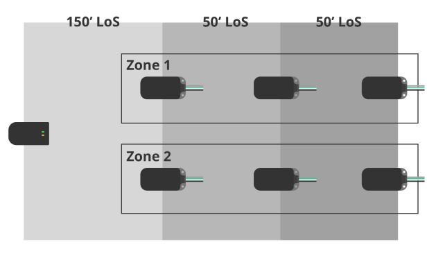
Network Range
Network range can be greatly affected by a number of factors, such as physical obstacles, radio interference and even elevation above ground. In order to achieve the optimal radio coverage, at least one dimmer in a zone has to be within 150 feet within the light of sight from the iCon. Furthermore, the antenna inside the dimmer has less attenuation if a dimmer is at least 5 feet above the ground. In addition, in a multiple dimmer system, the distance between each dimmer within a zone must be within 50 feet line of sight.
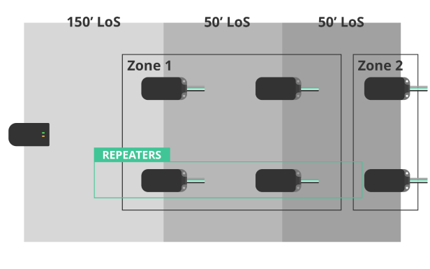
In situations in which a zone is out-of-range of the iCon and is also located behind another zone, multiple "dummy" dimmers can be used as "repeaters" to bridge the signal over from the iCon to the out-of-range zone. Connect only AC power to each dimmer and place them approximately 50 feet apart from each other until reaching the desired zone location.
Notice: The unused DIM+ and DIM- wire must be capper properly to avoid short circuiting.
Note: All devices must be at least 5' above the ground. LoS meaning Light of Sight.

Research, Development, Innovation
40 Vogell Road Unit #28
Richmond Hill, Ontario
L4B3N6 Canada
info@amptek-tech.com
+1 (905) 883 1000
© Amptek Technologies Inc.