
User Manual – iCon Sensor
Last revised 17 July 2017.
Notice: This product only works with the iCon Wireless Control Hub (WCH100) and BLE Dimmer (BLD100). Both are sold separately.
Status Lights
There are two status lights behind the PIR lens.
Yellow: PIR has detected motion.
Green: Ultrasonic sensor has detected motion.
Specs
iCon Sensor
Hardware
Input: 100-375VAC, 50/60Hz, 13A
Output: 100-375VAC, 13A Max, 4000VA Max
Infrared motion sensor range: 360 degrees, 5.5 meter radius
Ultrasonic motion sensor range: 4 meters
Bluetooth: Bluetooth Low Energy V4.2
Dimensions (Length x Width x Height): 122mm x 128mm x 36mm
Certifications
FCC ID: QOQBGM113
IC: 5123A-BGM113
ETL: Certified to CSA C22.2 No 60950-1, Conforms to UL Std. 60950-1.
Installing the iCon Sensor hardware.
The sensor works best when mounted between 2 and 2.5 meters high with a direct line of sight to the area of monitoring. It is also best to mount the sensor no more than 15 meters from at least one BLE Dimmer.
The sensor can be mounted on the ceiling or at a corner with the supplied brackets. When mounted at a corner, the bracket provides a 25-degree tilted down angle.

The ceiling bracket has four mounting holes. The two ceiling mounting holes near the center are 35mm apart, whereas the two corner mounting holes are 48mm from the corner. Use the provided wall anchors and M5 screws to secure the bracket.

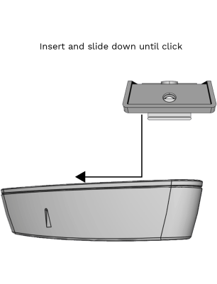
To mount the sensor on the ceiling, gently push the sensor into the T-shape latch and then slide the sensor towards the middle until you hear a click sound. Feed the wires through the rectangular slot in the middle of the bracket and connect to power. To remove the sensor from the bracket, gently press the lock at the back of the sensor and slide it off the bracket.
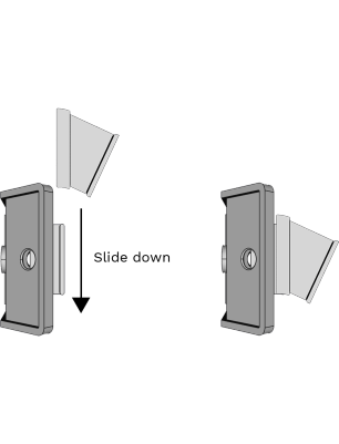
To connect the two brackets for corner mounting, slide the cornet bracket into the ceiling bracket as shown below.
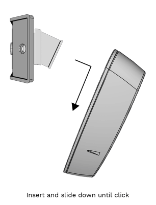
To mount the sensor at a corner, connect the two mounting brackets together and gently push the sensor into the T-shape latch at the corner bracket. Slide towards the middle of the sensor until you hear a click sound. Feed the wires through the rectangular slot in the middle of the bracket and connect to power.
A CIRCUIT BREAKER SHALL BE INSTALLED ON THE AC LINES SUPPLYING THE SENSOR. IF YOU ARE NOT FAMILIAR WITH AC ELECTRICAL WIRING, PLEASE ALLOW A LICENSED ELECTRICIAN TO PERFORM THE INSTALLATION.

Controlling the iCon Sensor.
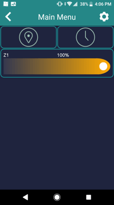
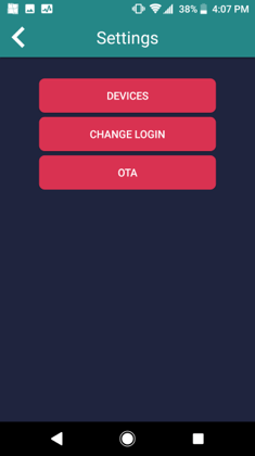
To configure the Occupancy Sensor, tap on the setup button at the top right corner of the screen.
Tap on the DEVICES button and select YES when a warning message appears.
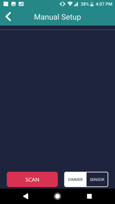
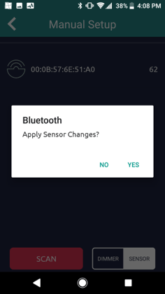
Walk close to the sensor that you want to configure and tap on the SENSOR button at the lower right corner of the screen.
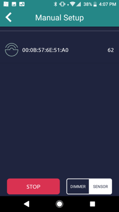
The app will list all Occupancy Sensors it can detect in the area. The sensor that is closest to the phone will be listed at the top of the list with the smallest number on the right. To select the sensor, simply tap on the sensor from the list.
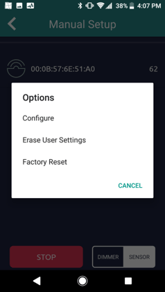
You will be given an option to configure the sensor, to erase al l user settings, or to reset the sensor back to factory. Tap on Configure and answer YES to continue. Both yellow and green status light on the Occupancy Sensor will be turned on once a connection is established.
If the opto sensor is enabled, you will be given the option to select three different levels of sensitivity. These levels of sensitivity correspond to the level of ambient light detected by the opto sensor. Move the slider to set the desire delay time (in minutes) for your lights. Tap on APPLY when you are done.
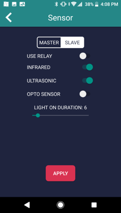
To store the setting to the sensor, simply tap on YES to complete the configuration.

Research, Development, Innovation
40 Vogell Road Unit #28
Richmond Hill, Ontario
L4B3N6 Canada
info@amptek-tech.com
+1 (905) 883 1000
© Amptek Technologies Inc.